Improvement for the AX-18A Smart Robotic Arm
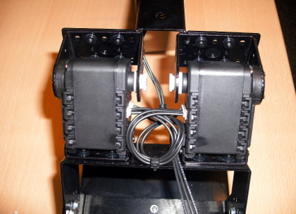
The DTPA research group from the University of Groningen uses many AX-18A smart robotic arms with 5-axis upgrade in student and research projects. It turned out that the shoulder joint of this robot is not strong enough. The AX-18A servo pair in the shoulder joint frequently trips on high temperature overload when stretching out horizontally just by carrying the arm its own weight. The shoulder joint is overloaded easily, even when the servo speed is carefully ramped up and down.
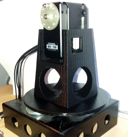
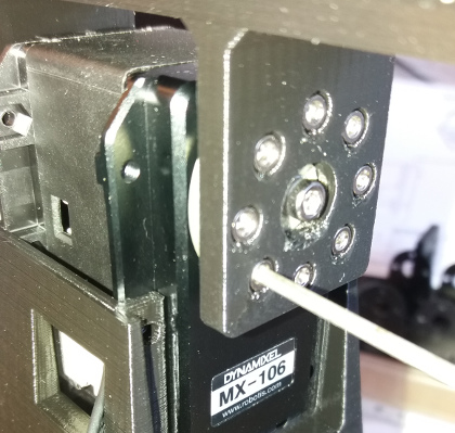
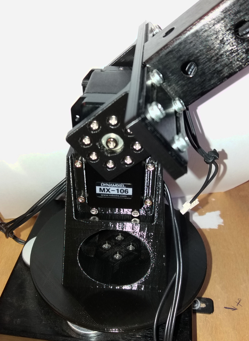
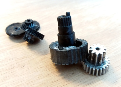
The AX-18A gears damaged several times, in particular the plastic gear on the output shaft that is driven by the aluminum gear. There is always one AX-18A from the servo pair that gets damaged, probably when one motor shuts down earlier than the other, causing a torque overload on the remaining active motor. A solution for this problem is replacing the AX-18A motor pair of the shoulder joint by a single, much stronger, servo motor. The design of two 3D-printed plastic parts can be found here for a complete replacement of the shoulder joint with a Dynamixel MX-106 motor.
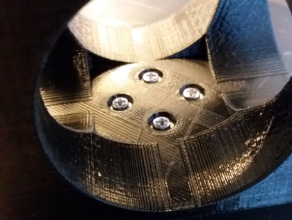
| Shoulder joint with AX-18A motor pair | Broken gears |
|---|---|
 |
 |
Motor replacement
The new stronger servo motor that was selected is the Dynamixel MX-106. It has metal gears and a metal front. The digital bus can be TTL (MX-106/T 3-pins) or RS485 (MX-106/R 4-pins). The T-version can be combined with the existing digital bus.
Stand
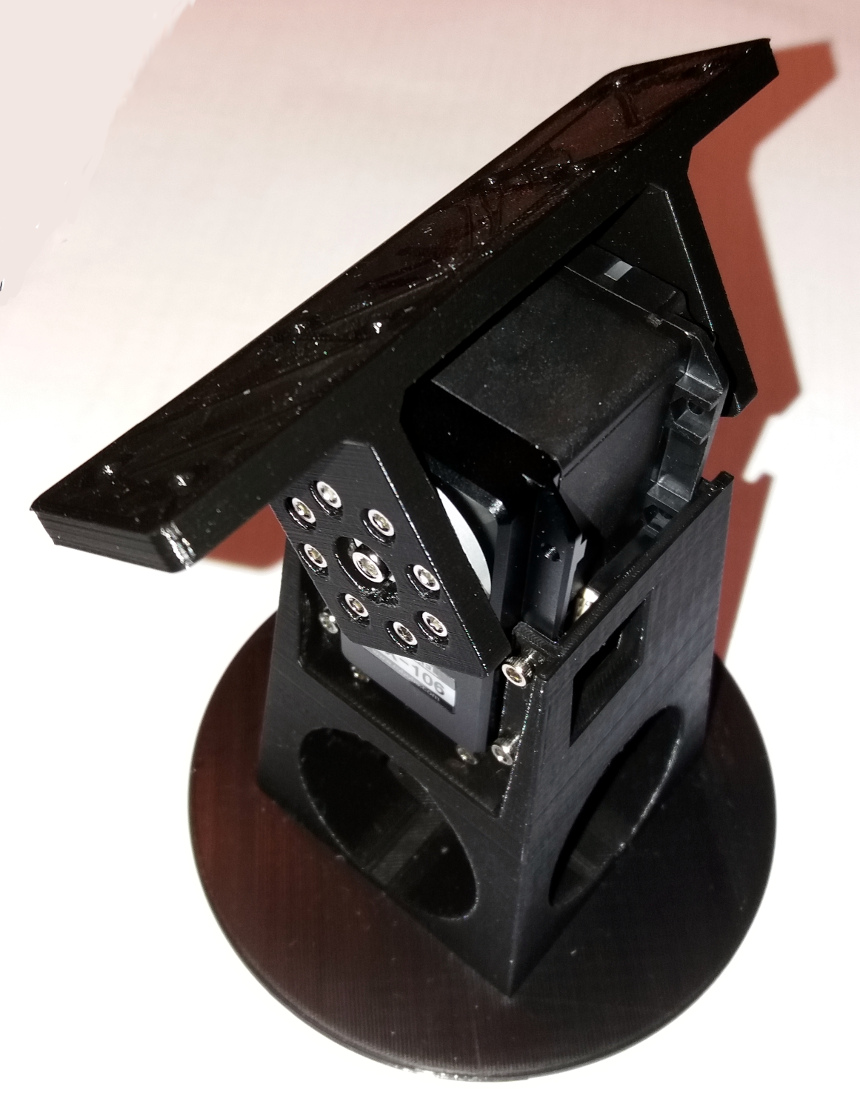
The stand is the part between the turn-table and the MX-106 shoulder servo motor.
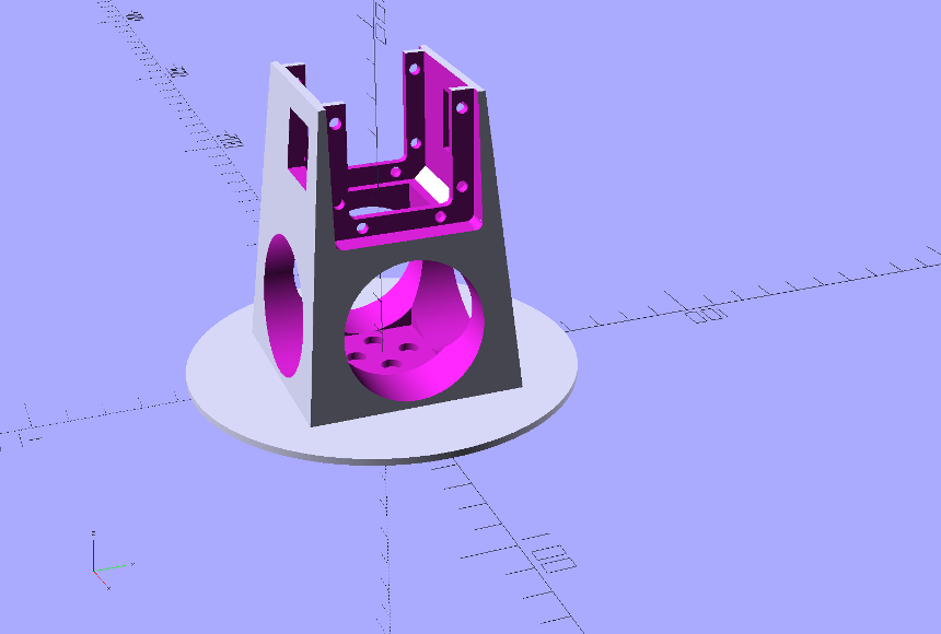
Bracket
The bracket part connects the servo horn to the main beam of the arm.
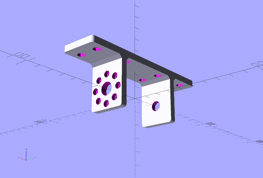
Assembly
For the prototype, the Stand and the Bracket are printed with black PLA material on the Ultimaker2+ 3D-printer. Follow the next steps to do the upgrade:
- Remove the original lower brace from the turntable. Put the new stand on top of the turntable and fix it with the original screws and washers.
- Push the MX-106 into the gap from the stand. The connectors must be accessible from the gaps in the front and back side of the stand.
- Fix the MX-106 metal front side with the Allen screws included in the motor kit. Eventually place screws at the back side, firs by gluing nuts behind the mounting holes in the rim of the motor housing.
- Install the servo horn as described in the documentation of the MX-106. Don't place the screw into the horn yet. Push M3 hex nuts in the holes of the bracket.
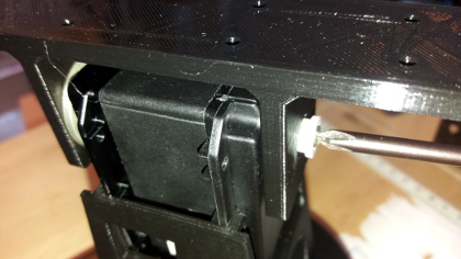
- Put the original AX-18A pivot spacer over the bulge at the back side. Place the bracket onto the horn. Push the AX-18A pivot through the hole at the back side of the bracket and fix it with a screw. Make sure that the bracket rotates freely around the Pivot. Lubricate with silicon based oil.
- Install the servo horn screw.
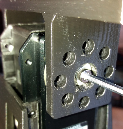
- Screw the bracket onto the servo horn.
- Mount the main beam to the bracket with 8mm M3 bolts with washers and spring washers.
Testing
To prevent damage, configure the angle limits of the motor, set the values for P, I and D properly and limit the torque. Consult the MX-106 manual about how to do this.
